There has been much misinformation and misunderstanding around so-called ghost frames. There is no frame type or subtype in the 802.11 standard called a ‘ghost frame’, but rather it’s a byproduct of frame reception that happens by way of 802.11 protocol design around 802.11 Basic Service Sets (BSSs). Before the ill-named concept of a ghost frame can be defined, a concept from the 802.11 standard must be presented.
PPDUs Use Multiple Data Rates
802.11 frames are transmitted at 1, 2, 3, or 4 rates (during the course of the transmission of the frame). Let’s first look at PPDU frame structures, from the oldest to the newest, starting with DSSS from 802.11-1997 and again later in 802.11-1999.

Fig 1. Direct Sequence Spread Spectrum (DSSS), from 802.11 Prime
In the Fig 1 frame format, the PLCP Preamble and the PLCP Header are transmitted at 1Mbps, and the MPDU (which is later called the PSDU) is transmitted at 1 or 2Mbps. This means that DSSS PPDUs are transmitted at 1 or 2 data rates.
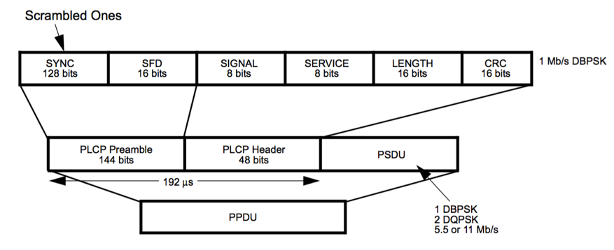
Fig 2. High Rate Direct Sequence Spread Spectrum (HR/DSSS), Long Preamble, from 802.11b
In the Fig 2 frame format, the PLCP Preamble and the PLCP Header are transmitted at 1Mbps (for backwards compatibility with 802.11 Prime), while the PSDU (formerly the MPDU) may be transmitted at 1, 2, 5.5, or 11Mbps. This means that HR/DSSS (Long Preamble) PPDUs are transmitted at 1 or 2 data rates.
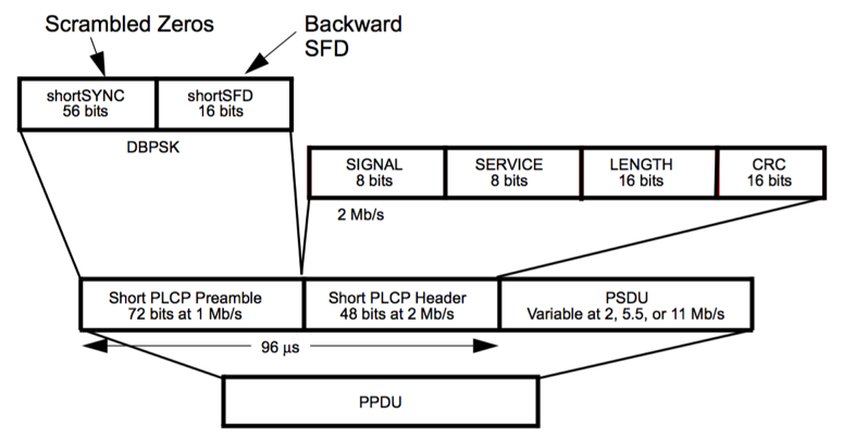
Fig 3. High Rate Direct Sequence Spread Spectrum (HR/DSSS), Short Preamble, from 802.11b
In the Fig 3 frame format, the PLCP Preamble is shortened to 50% of its previous length but remains at 1Mbps. The PLCP Header remains at its previous length but is now transmitted at 2Mbps. This formatting breaks backwards compatibility, so APs have to indicate when Long Preamble Only clients (802.11 Prime and 802.11 HR/DSSS with Long Preamble) are present within the BSS so that all clients (and the AP) will use long preambles. The PSDU is then transmitted at either 2, 5.5, or 11Mbps. This means that HR/DSSS (Short Preamble) PPDUs are transmitted at 2 or 3 data rates.
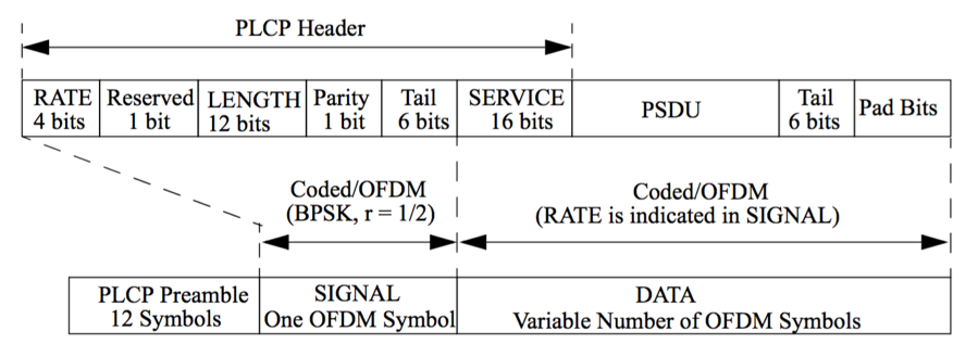
Fig 4. OFDM (802.11a) and ERP-OFDM (802.11g)
In the Fig 4 frame format, the PLCP Preamble and SIGNAL field is transmitted at 6Mbps, and the PSDU (and surrounding sub-fields) are transmitted at the data rate specified in the RATE field, which is 6-54Mbps. This means that OFDM and ERP-OFDM PPDUs are transmitted at either 1 or 2 data rates.
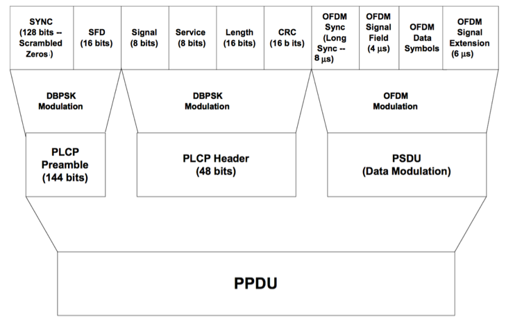
Fig 5. DSSS-OFDM (802.11g) with Long Preambles
In the Fig 5 frame format, the PLCP Preamble and PLCP Header mimic that of DSSS and HR/DSSS (Long Preamble), using 1Mbps data rates (for backwards compatibility). The OFDM Sync (preamble) and the OFDM Signal Field are both transmitted at 6Mbps as with standard OFDM. The OFDM Data Symbols (the payload) is transmitted from 6-54Mbps. This means that DSSS-OFDM (Long Preamble) PPDUs are transmitted at either 2 or 3 data rates.
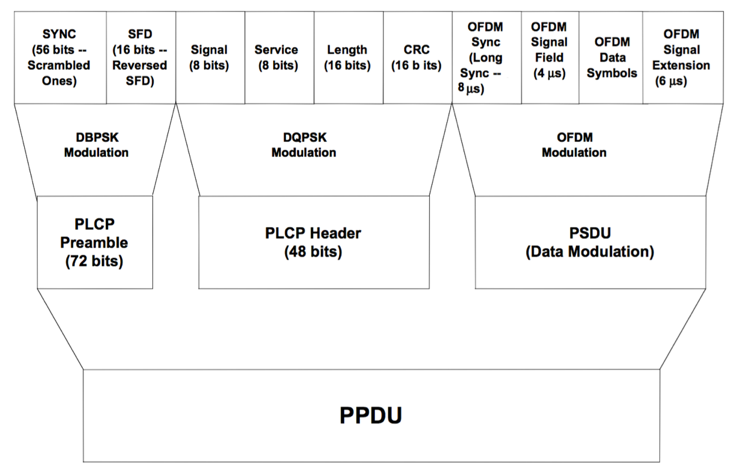
Fig. 6. DSSS-OFDM (802.11g) with Short Preambles
In the Fig 6 frame format, the PLCP Preamble and PLCP Header mimic that of HR/DSSS (Short Preamble) with 1Mbps and 2Mbps data rates. The OFDM Sync (preamble) and the OFDM Signal Field are both transmitted at 6Mbps as with standard OFDM. The OFDM Data Symbols (the payload) is transmitted from 6-54Mbps. This means that DSSS-OFDM (Short Preamble) PPDUs are transmitted at either 3 or 4 data rates.
Since 802.11n, 802.11ac, and 802.11ax are all based on OFDM, the same operational rules apply to them, so there is no need to go any further than 802.11a for the purposes of this discussion. The point of this section was to show that PPDUs are not transmitted at a single data rate.
What Is A “Ghost Frame?”
Ben Miller’s concept of a ghost frame is defined distinctly as:
Any frame transmission where only the PHY header can be decoded by a receiver.
Just for clarification, you could say it in a slightly different (and longer) way:
Any transmitted frame whose PHY header data rate differs from its MAC and/or PAYLOAD data rate so that at a given distance from the transmitter, a receiver could only receive the PHY header.
That definition applies to all frames (and frame types) transmitted by any 802.11 transmitter, that are using a MAC/PAYLOAD data rate >1M or >6M (depending on band), whereby only the PHY header is decodable by a receiver. If the expression ‘ghost frame’ was initially meant to be an avoidable exception, it certainly isn’t.
With his own illustration, Ben cements his definition.
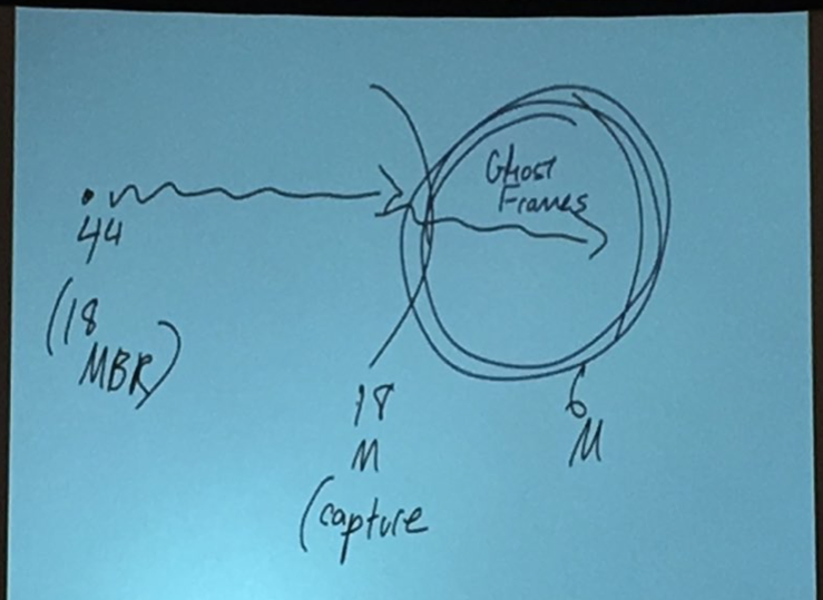
Fig 7. Ben Miller’s Own Illustration of His Definition of ‘Ghost Frames’
This concept goes much further than how Ben tries to position it, as I will explain below. Consider, for the time-being, all of the variables involved in whether a receiver can receive the PHY header, but not receive the MAC/PAYLOAD:
- Receiver sensitivity
- Receiver position/distance
- FSPL and RF loss from objects in the environment
- Output power of transmitter
- Data rate (MCS rate) of MAC/PAYLOAD transmission
Examples:
- You could have a transmitter sending an OFDM PPDU at 6M/54M to a receiver that has very low sensitivity, and the range at which the 6M PHY header would cause backoff would be much larger than the decodable range of 54M.
- You could have a transmitter sending an OFDM PPDU at 6M/9M to a receiver that has very high sensitivity, and the range at which the 6M PHY header would cause backoff would be negligibly larger than the decodable range of 9M.
My point is that it’s continually and inexplicably variable, across all frame types, and manifestly unavoidable.
Do Ghost Frames Matter?
Ben asserts that the problems caused by PPDU multi-rate are:
- An 802.11 receiver (or capture application) cannot decode the frames that are using a MAC/PAYLOAD data rate above 6Mbps when positioned outside the data rate’s decode boundary for that particular receiver.
The data rate decode boundary is dependent on a receiver’s receive sensitivity, and every receiver is different. This means that every receiver (AP or client) has a different set of data rate decode boundaries: 1) from every transmitter (AP or client), 2) for every transmission, and 3) of every frame type. This isn’t a problem, but rather simply how WiFi is supposed to work.
- The PHY header’s LENGTH (or RATE and LENGTH with OFDM) cause receivers to back off

First, the LENGTH (or LENGTH and RATE for OFDM) determine PHY layer backoff for the frame currently being transmitted. DURATION in the MAC header is different in that it causes receivers to back off for the duration of the entire frame exchange unless the MAC frame is destined to their own MAC address. The LENGTH (or LENGTH/RATE) (Layer 1) work in unison with the DURATION field (Layer 2) so that all frames are protected, including initial frames in a frame exchange sequence. The area past the physical MAC/PAYLOAD decodable boundary, while still allowing the PHY header to be decoded, for any given transmission, for any given receiver, becomes continually variable based on continual data rate changes, receiver sensitivity, and possibly a moving receiver. While it does in fact cause contention, it is not a concept that we can plan our networks around.
Ben also asserts that we need to understand the decodable range of each BSA (basic service area), all the way to the 1M (DSSS) or 6M (OFDM) rates (depending on the band in question) due to the possibility of receiving only PHY headers. I refer you to Fig 8 below, where in Ekahau ESS I have configured a Cisco 2702i for 1mW (0dBm) Intentional Radiator (IR) power, positioned at one end of 5 American football fields (120 yards each), scaled properly (for a total of 600 yards or 549 meters). The one-way normalized (FSPL only) voice-grade coverage area for -65dBm on 2.4GHz is ~30 yards, while the interference area (down to ~4dB SNR @6Mbps) is ~600 yards. If you extrapolate for best-practice power output, two-way normalization (includes receiver sensitivity in the math) for a 2×2:2 receiver, and a 20MHz 5GHz channel, you quickly come to the conclusion that not only are these 6Mbps boundaries a really long way from a transmitter, but so are even higher data rates such as 9, 12, and 18Mbps.
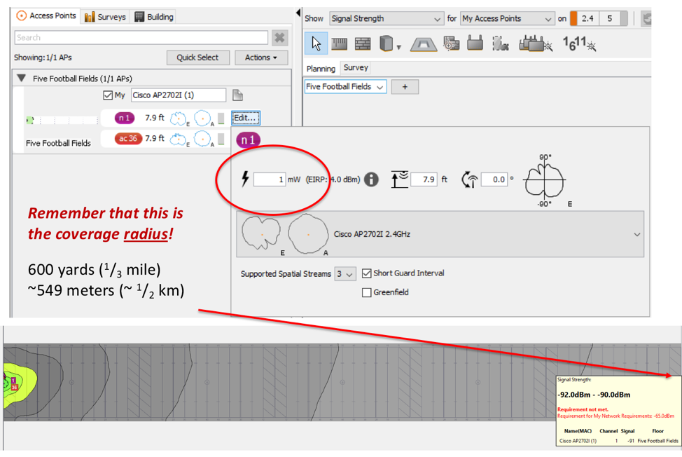 Fig 8. Minimum Decodable Data Rate Range, One-way Normalized
At 2.4GHz, we often use 6-10dBm IR power (on the AP) and usually have 3-4dBi antennas. You can quickly see that the contention range, if the signal is not blocked by many walls (and other loss objects) is extraordinarily large.
At 5GHz, we often use 10-14dBm IR power (on the AP) and usually have 4-5dBi antennas. 5GHz experiences an additional 7dB of loss in the first meter with omni antennas, and since the Inverse Square Law, when in open space, defines loss at -6dB for every 2 times the distance (2D), then we can roughly estimate that 5GHz has half of the usable range and contention range of 2.4GHz. In this case, “roughly half” would still be enormous.
With a sensitive receiver (e.g. a 3×3:3 laptop), the contention range for either band is so large, without numerous, lossy walls to block the signal, that consideration of the PHY vs. MAC/PAYLOAD data rate differential is inconsequential.
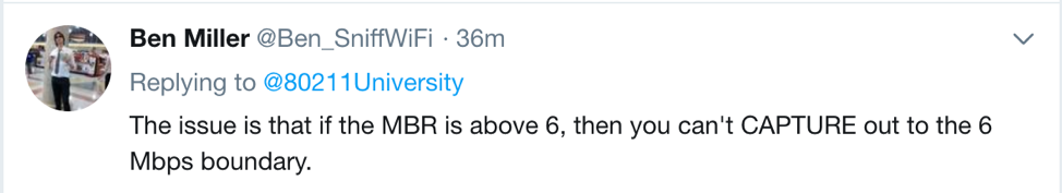
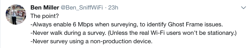
Ben’s assertion (below) that we need to enable 6Mbps data rates for surveys is unnecessary, as I will clearly explain in the next section.

Three Causes of Contention (CCI)
Because APs aren’t the only transmitters in an ESS, there are three causes of contention (not counting ACI or non-WiFi interference), that I call Intra-BSS, Inter-BSS, and Client-to-Client (or Client-to-Opposing-AP). These three types are illustrated in Fig 9 below. There is far more contention on your network than you may think, especially if you didn’t take the time to design and validate it.
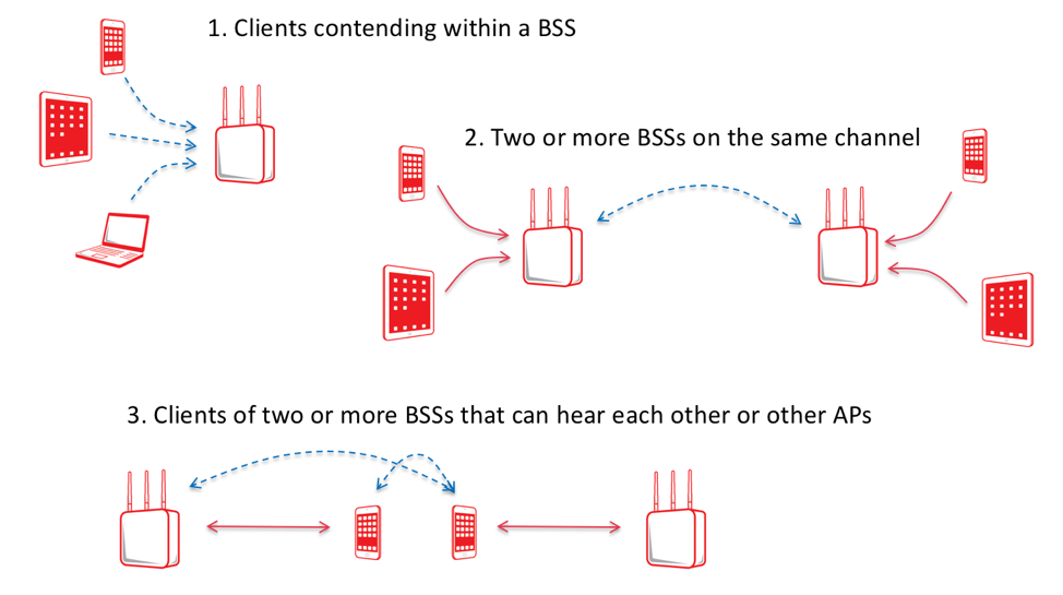
Fig 9. Three Causes of Contention
The reason that mentioning the three causes of contention is to support my assertion that clients cause a much larger contention area than APs do, for a given BSS.
The contention radius of a BSS is primarily determined by:
- Client group position around the AP, which includes distances from the AP
- Output power of the AP
- Output power of the client group
- Receiver sensitivity of the associated clients
- Receiver sensitivity and location of any nearby receiver, who is not in the BSS
- Preamble & PHY header modulation type (BPSK)
- Any loss objects between a transmitter and receiver
There are also some modest causes of contention, such as:
- AP’s Minimum Basic Rate (MBR), as this will positively impact clients that do not roam well, serving as a hard boundary (per client) for forced roaming.
- The primary reason for raising the MBR is to decrease airtime consumption of management frames such as beacons and probe responses.
Given a client transmitter between the AP (to which it is associated) and a nearby receiver (that is outside the BSS), client transmissions will be far louder to the receiver (and decodable at a much longer range than AP transmissions) due strictly to the effects of FSPL on AP transmissions, as shown in Fig 10 below.
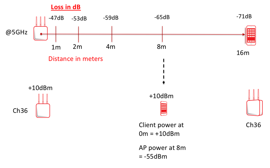
Fig 10. 5GHz FSPL Math Example
AP transmissions are the primary cause of contention (from a BSS), as shown in Fig 11 below, when:
- There are no associated clients
- There are no associated clients in a given direction, whereby the AP is the closest transmitter to a receiver
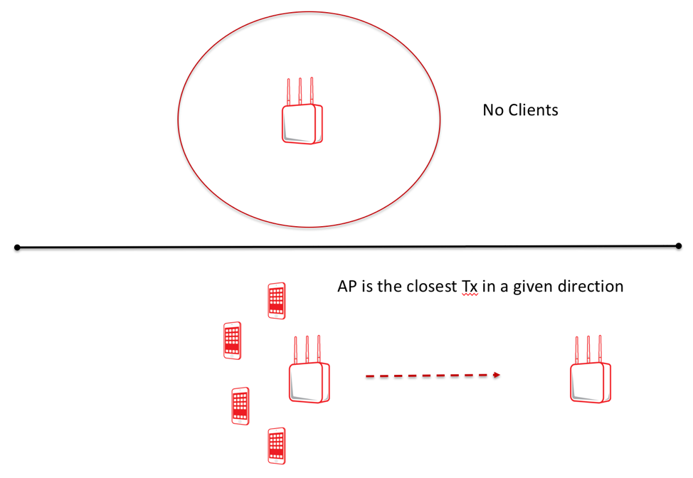
Fig 11. When AP Transmissions Are the Primary Cause of Contention (from a BSS)
Ben’s counter-point to my assertion that clients are the primary causers of contention from a BSS (within an ESS), is that APs transmit more data (and therefore more often) than clients do, and if his assertion alludes to any single client, then he is generally correct. If his assertion alludes to all clients collectively, then that is only partially correct because it depends entirely on the situation at any given moment in any given network. My argument is that it doesn’t matter whether Ben is fully or partially correct about the percentage of airtime consumption by individual client devices or all client devices collectively within a specific BSS. My rationale is two-fold: 1) As shown in Fig 12 below, that client devices meaningfully, continually, and variably extend the contention range of a BSS in such a manner that where InterBSS contention may not be present in an ESS, Client-to-Client and/or Client-to-Opposing-AP contention very likely is present – the amount of which depends on the situation, and 2) all downlink (DL) data has to be acknowledged in the uplink direction. Whatever the percentage of airtime that is consumed by client devices within the BSS, that is the amount of airtime lost in other same-channel BSSs within the ESS. You cannot put a single BSS in a box and say what applies to it applies generally to the entire ESS because ESS design is rarely perfect for a variety of reasons. My friend Chuck Lucaszewski says (paraphrasing), “You have a channel reuse factor of 1 unless you can prove you don’t.” That means that you have contention (aka CCI) unless you can prove you don’t. Client-induced contention is the primary cause.
An additional consideration is that enterprises are very rarely confined to a BSS, but rather have many BSSs within an ESS. Each BSS within the ESS has transmitting clients at given ranges from their associated AP, and with the limited number of 5GHz channels available, it is very difficult (especially in multi-floor environments) to get rid of 5GHz contention. It’s nearly impossible to get rid of 2.4GHz contention in such environments. The further client devices move from an AP, the more contention they cause to neighboring same-channel BSSs within reception range. If we had no clients, it would be difficult to rid ourselves of 5GHz InterBSS contention, but with clients present and mobile, it is nearly impossible to get rid of contention. The amount of contention caused by PHY data rates differing from MAC/PAYLOAD data rates pales in comparison and is in fact altogether ‘in the noise.’
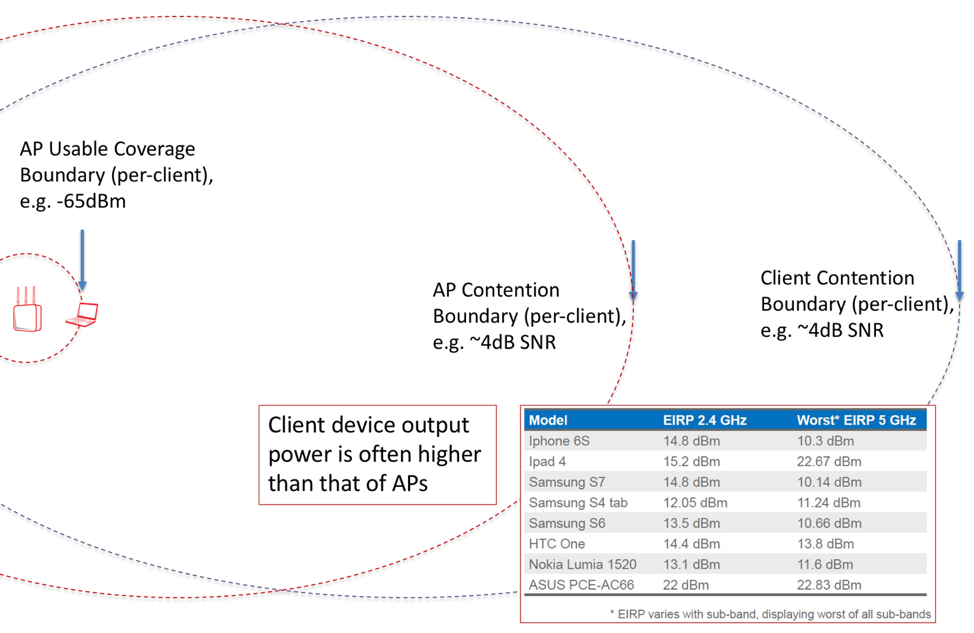
Fig 12. Client-induced Contention Extends the BSA Contention Area
The more active clients that are in a BSS, the more of the airtime is consumed with uplink transmissions, at a greater distance than the AP’s contention boundary, causing contention for any neighboring same-channel APs and clients. In Fig 12 above, the reference to “~4dB SNR” for the contention boundary comes from a detailed discussion here.
Using RF Design and Survey Software
Ben has asserted on many occasions that we need to know the contention range of each BSS for design purposes, but he doesn’t advocate using RF modeling or RF survey software. Instead, he advocates that all surveys should be done only with client devices, whereby heat maps are not available. The industry at large disagrees with this approach because we can, in fact, offset our RF designs and RF surveys for the “least-capable, most important” device (or said another way, the least-capable device that is important to the customer). You can find out more about that here. While today’s RF modeling tools help us reduce InterBSS contention, and design best practices help us reduce IntraBSS contention, we do not currently have tools that will indicate Client-to-Client contention. Manual surveys, using actual client devices (as Ben suggests) will allow us to assess Client-to-Opposing-AP contention, but that’s still not the entirety of the contention domain. I have done such manual surveys in the past, and they were helpful, but of limited use because they give the customer no verifiable data. This is why we use RF Site Survey software.
Ben has also asserted that the antennas used in RF Site Survey kits (USB NICs, Sidekicks™, etc.) aren’t the same as those of client devices, and therefore survey data is wrong. I disagree because we use measurements from the customer’s actual client devices to offset our RF Models and RF Site Surveys, so that our heat maps look as any given client device would experience the RF environment.
Corrections to Ben’s Blog on So-called Ghost Frames
Below, is an excerpt from Ben’s blog on so-called ghost frames. The LENGTH field in an OFDM PPDU denotes the number of octets (bytes) the payload (PSDU and surrounding subfields) will be, and the RATE notes the MCS to be used for the payload. Together, they detail how long (in time) that it is estimated by the transmitter for THIS FRAME to make it across the air. The RATE/LENGTH (or just LENGTH in DSSS and HR/DSSS, which is interpreted as time in microseconds) is used to protect THIS frame transmission, and to force any station who can hear it to be quiet until such a time as they receive the rest of the frame. Once the MAC header is processed, they know whether or not to: 1) respond (because the transmission is for them), or 2) to be quiet the remainder of the entire frame exchange (which is denoted by the DURATION value in the MAC header). All of this is by design, and it is not a shortcoming of any kind. The airtime loss that Ben describes below is an inconsequential side effect of backwards compatibility and caused when a receiver is outside of the decodable range of the MAC/PAYLOAD of a frame.
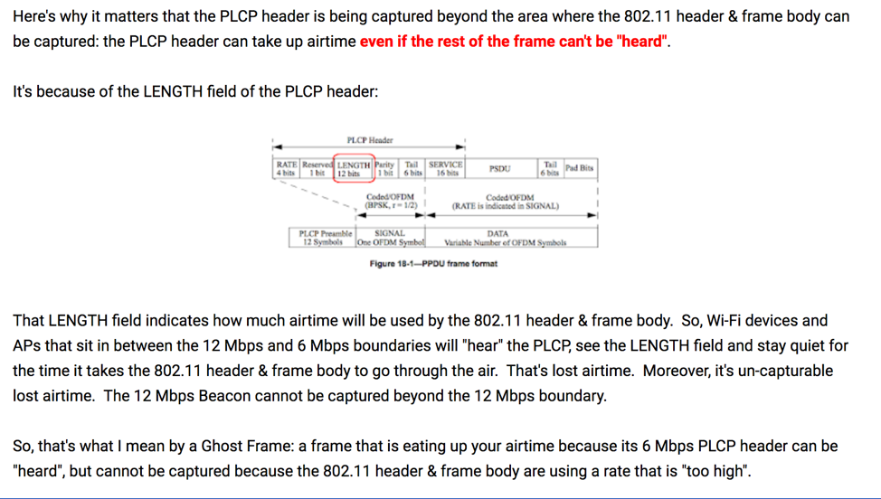
Fig 13. An Excerpt from Ben’s Blog On Ghost Frames
Summary
While there is no 802.11 frame type called “ghost,” the concept of a PHY header being received when its MAC header and payload cannot does exist. No frame is transmitted as a ghost frame, rather the term ‘ghost frame’ as given by Ben Miller alludes to a receiver affect (described above) that may cause an inconsequential contention effect, for any frame type, that the 802.11 protocol designers purposefully intended to protect frame transmissions. In my opinion, the concept is misleadingly named (for marketing purposes) and irrelevant to Wi-Fi design, deployment, and validation.